Monday, May 3, 2021

Further exploration

So, have been putting the new amp through its paces, learning its voice and how it interacts with the MC5 and the Line6 Pod HD effects unit. Tonally, it's a lot different sounding than the first amp ("Scarlett"), of course: much more mid-frequency focused, no doubt due to the cathode bypass capacitor and coupling capacitor values that reduce the low end, and the cool-biased, all-12AY7 (tube type) pre-amp seems to compress the dynamics a bit, so note attacks and articulations are a bit softer. And while it is bright enough sounding, it doesn't have Ruby's sparkliness in clean settings.  The range of tone settings of the preamp feels a bit limited compared to Ruby, but that may have more to do with the aforementioned bypass and coupling caps, than the components of the tone section of the circuit. Nevertheless, I may try reducing the value of the capacitor governing the mid pot, to roll off a bit less of the low end there. At about 7 on the preamp "gain" dial, the clean tone develops a nice edge to it, and progressing up to 10 adds a slight crunch when I dig in to a string, especially in humbucker setting on the MC5. That said, I'd still characterize it as remaining quite inside the realm of "clean" for single coil and non-aggressive playing. Just as I hoped it would.

The OD (overdrive) circuit is fascinating, though I'm still figuring out how to consistently get sounds I like from it. As you may recall, it is a cascading pair of triodes (again, 12AY7) which takes its signal input from the output of the preamp. When the preamp gain is high, the OD input is also high and can drive the first OD triode to the point of clipping, or flattening, the highest amplitude portions of the audio signal. But with the preamp at lower gain settings - below 50% - the first OD triode gain remains mostly linear and simply shapes the tone of the signal, further reducing low frequency content and softening the highs. The "drive" dial controls the amplitude of the signal coming from the first OD triode and presented to the second, and allows fine control over further distortion of the signal, from a very clipped high gain sound (depending to a large extent on the shape of the incoming signal) to a fairly clean punchy mid-boosted sound. After that, a single "tone" dial allows for attenuating the high frequencies and preserving the lows, and a "level" dial adjusts the final signal strength passed back into the main circuit. 

Using the Line 6 HD-500x signal processor for adding effects such as stereo reverb, delay, L/R panning, etc., in the FX loop part of the circuit has worked well so far, especially considering the range of input voltages is has to handle, from a few hundred millivolts to a couple of volts. The HD apparently adjusts automatically to the incoming signal impedance. This is not true of the pedal effects I have, and they do not work well in the FX loop. I can run the single channel "send" to the HD and return a right and left stereo signal to the power section, or return just one channel from the HD as a mono effect, and leave the other channel dry (un-effected). Both methods work well, and as planned. 

The power section stays quite clean and crisp up through reasonable volumes and only begins to break up at ear-splitting levels. With the attenuator (Fryette PS2) in place to keep the final output volume down, I can activate one channel and dial the power section up to the point of near break-up, which is a nice sound - probably one I would use for recording, but not in a live setting because it's requires too much fiddling around. Here's the circuit in its current implementation (without the power supply):


I recently received a new speaker to try in place of one of the stock 12" Fenders that came with the FM212 salvage amp. Based on my positive past experience with a 2x10 stereo combo, I opted for a 10" speaker that is shown to have a relatively balanced response: the Eminence Cannabis Rex. I created and installed a second baffle behind the existing one on the right side of the amp, mounted the speaker, and have been playing it on its own and in combination with either the stock 12" Fender mounted in the left side of the amp, or an EV-L 12" mounted in a separate Thile-optimized cabinet. I like the new speaker so far, but I'll have to do some recording and listening back to be sure it's what I'm aiming for.


(new 10" speaker test)


Saturday, April 24, 2021

Initial testing

I fired it up with the "lamp limiter" in place (200w lightbulb in series with the incoming AC power, allows full voltage, but limits the maximum current that can be drawn by the amp, preventing damage from major shorts, etc.), first with no tubes, then with tubes installed... No smoke or fire! always a welcome sign. I measured voltage in some important spots and found things to be in line with readings from my test board set-up. Here's the working circuit:


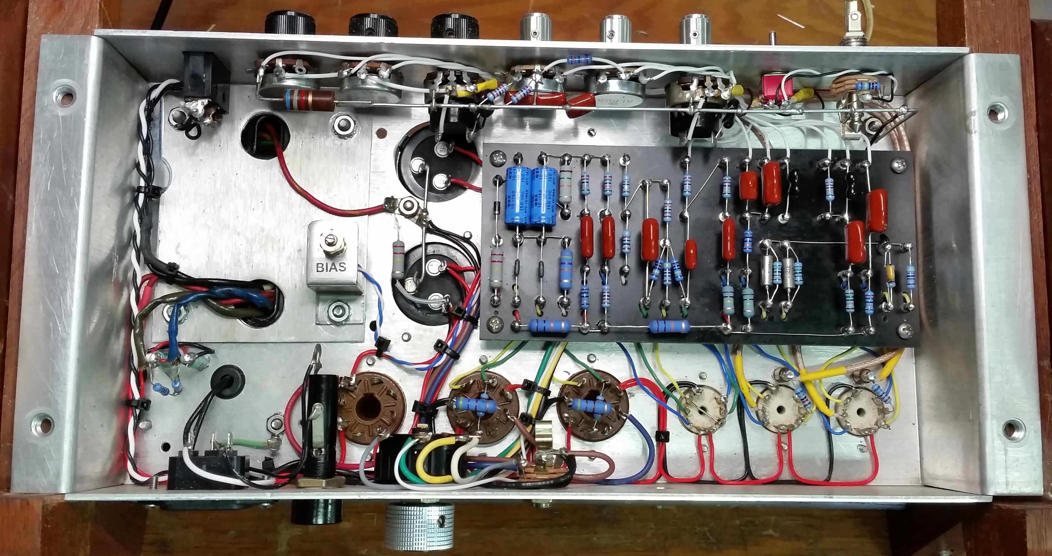
Removed lamp limiter and plugged in a guitar, and (once again, shockingly) everything seems to work as it should. Stereo master volumes, OD channel and pre-amp switches work as expected, all controls, work fine. Well, almost - I had to fix one error, and make one adjustment: I had mis-wired some jumpers on the left and right channel volume pots such that the dials worked in reverse - an easy fix. Also, because I implemented a slightly different DC filter design than I had in my test board, the screen voltage on the power tubes was lower than expected, lowering the max output of the tubes, and (as we learned in an earlier post) compressing the signal slightly. So I reduced the resistance in one part of the filter circuit, and that fixed it. Here are some "final" pics, tho the OD circuit will probably need some tweaking as I play with it more.


(rear view of chassis)

... with chassis installed back in the cabinet.


Wednesday, April 21, 2021

Details

I'll have to digress slightly at this point to acknowledge some things. 

The folks who make this stuff look easy, repeatedly, are truly master crafts-people. That may be obvious to some, but for me - a habitual, sometimes recovering, scoffer - I admit it has taken a while for this to really sink in. I continue to struggle, after many months of trying, to keep things straight and neat, to work efficiently, to make sound and consistent solder joints, and to layout my circuits in a way that supports ease of assembly as well as a short signal path. Even working slowly and deliberately, completing just one task to the level quality that I'm aiming for, is a rare thing... and there are hundreds of such tasks required in succession to build a high quality piece of gear. It borders on frustrating at times, but only for a moment, and then I realize it doesn't matter how long it takes, or whether some theoretical customer would  be happy with it. Mentally, I am so habituated to pursue optimization of cost (time), features, and quality, that it takes real focus to shift away from that holy trinity of commercial product development toward something more personally nourishing... the optimization of time spent with my sweetheart, enjoying the process of learning, solving, and creating, and being ever more mindful of my role and responsibilities in the family of earthly things. 

My understanding of "Lead Dress" is that refers to the concern for and execution of proper placement of wiring and components to achieve desired circuit dynamics and audio results. It isn't just precise adherence to the circuit design or the neatness of the installation, though both of those are critical for a successful build. Rather, it's a very deliberate approach to the organization and connection of parts that sounds best/right, and results in a physically robust build that is straight-forward to maintain. Making good lead dress takes a lot of practice. Here are some links to examples of solid lead dress. 


(Michael's amp)


(Hoffman Blackface Deluxe)


(Trinity Tri-watt)


(Sluckey Amps All American Dual Lite)

Good looks and stage appeal, while not required, also don't hurt. It's enough to be masterful on the electronics side, but some folks are also excellent wood workers, upholsterers, and visual designers as well. Three more areas in which I know just enough to injure myself, yet lack the depth of skills and patience required to produce something of value to anyone other than myself... which gets back to the previous point regarding this whole enterprise being about process and learning and less about specific outcomes, I suppose.

So, lots of progress since last post: 

Rigged up a mounting bracket and two LEDs to work with the two relays using the tiny holes already in the front panel: 


Pre-wired and installed all front panel controls:


Wired the main circuit board and set components:


Installed circuit board and connected all leads to controls and sockets:


Pre-start up sequence and testing is next. Then we'll see how it sounds...


Wednesday, April 7, 2021

Footswitch and relays

Got the 5v relay circuit up and running.  Also added two micro switches (for overdrive and pre-amp boost) on the far left of panel as manual relay controls for use if the footswitch is not plugged in. Tested and all seems to work as designed. 


Indicators: I'll need to have a visual indication of what switches are engaged at any given time, and of course, many amps put lights on both the footswitch and the front panel to aid players. It turns out that rigging up the indicator LEDs to work on the footswitch itself is more involved than one might first guess, so I'm opting for just having them on the front panel. I did some testing with salvaged LEDs and I think it should work fine to utilize the same holes used for this purpose by the old amp - just need to find the right size LEDs (the leads on the salvaged ones are too short for me to work with - see pic), and with some glue and attachment gymnastics, they should be both functional and also maintainable down the road. 


One reason I picked the Frontman 212 as the salvage model, was that its front panel nicely accommodates the needs of my design in terms of holes for jacks and pots. You can see I won't really have to do anything to the front panel to get all my stuff in there, and a lot of the labels even match mine. 


I haven't decided on front panel treatment yet:

  • Whether to try to find a way to update just some of the labels as needed... or all of them with a strip of something across the whole bottom. Hard to imagine that looking very good. 
  • Replace the whole thing - it will peel off in one piece and I can use it as a template - but getting something decent made isn't cheap, and I'm not sure I want to do another DIY one like I did for the 5F6A/JTM. 
  • Just leave as is - most likely outcome, and I like that no one will see it and think it worth stealing (the FM212 is a cheap amp, not well reviewed).

Also, got the footswitch and cable put together and tested. The 5v system works as it should up to this point - just need to receive the indicator LEDs, install and test. 


Sunday, April 4, 2021

Power supply and OTs

Some progress: I installed the tube sockets, and got the power supply and main filtering part of the circuit up and running.  I sorted out the exact location of the output transformers and installed those. It's coming together. 

When I checked tube clearances I discovered that the plastic bases of the power tubes were just touching the adjacent aluminum angle brace, so had to pull things apart and make a few bends in spots to be sure the tubes will have enough space around them and certainly not be in contact with the chassis. I think I will add some tiny metal straps to hold the tube rail and the angle brace together - with that big long hole cut out of the back of the chassis, there's  more flex now in the floor, and with the added weight of the two output transformers, things are moving around a bit. 

I brought the wall power up to a full 119 volts (AC) and measured an unloaded B+ of 348 volts DC entering the filter section from the rectifier. I think that's right in line with my test circuits. I also measured 6.7 volts AC on the taps feeding the filament circuit and relays, so all seems to in order. 

(fully wired PT and filter circuit)


(tube sockets and OTs installed)


(reinforcing bracket, aluminum tape, impedance switch and speaker jacks added)


Tuesday, March 30, 2021

Footswitches

The circuit design on which I'm basing mine includes an overdrive (OD) feature: the input signal is amplified and shaped by a pair of preamp triodes and is either passed as a "clean" signal to the power section or diverted to a second pair of triodes, the OD section, before then getting routed to the power section. (It's important to note that the OD feature is most useful for lead/melodic playing, but not for playing chords to accompany a tune - at least not to my ear... the distortion created by the OD can make it hard to distinguish relationships between multiple notes, so it's less desirable for chords more complex than simple triads). If this amp is to be used for live playing, then I'd like to be able to easily switch between clean and OD during the performance of a piece, when reaching to a switch on the front panel of the amp would be impractical. A remote footswitch is a commonly implemented solution for this problem - all of the amps I've owned have had this feature... one I have taken for granted until having to design and build it into an amp myself.

Switches mounted on the front panel of an amp, such as those I included in my first build, typically carry and route the guitar signal this way or that through the amp. But, in the case of a remote foot switch design, we're moving the switch outside of the protection of the chassis, far from the delicate audio circuit, and adding a dozen or so feet to the length of the signal path. This would be likely to degrade the quality of the signal and introduce noise into the circuit - it's really just not done as far as I know, at least not in modern amps. Instead, we make the footswitch simply an actuator that controls an electronic switch that is inside the chassis, which keeps the signal path short and protected. To do this, we need an actuator for each switch and access to a power supply to drive them. It's not that hard to do, and it's been done a jillion times, but it IS a separate subsystem in the amp that requires it's own design and implementation effort, and wasn't something I had thought that much about before now.

In my design, even though I've got 3 switches in the circuit (Bright / Pre-amp Boost (PAB) / OD), I already have a two-button foot-switch that came with the salvaged Fender amp, so I'll just implement two of them, the PAB and OD. I also want to be able to actuate them in the usual way, with switches on the front panel, AND I'd like to have some visual indicators that tell me if each switch is on or off - LEDs will do. Here's the newly added section of the schematic that describes this additional subsystem.

Everything to the right of the lamp is newly added to support a pair of footswitches for the PAB and OD, as well as the associated panel-mounted switches.

Here are the bits and bobs needed to implement the switches: salvaged footswitch unit, relays and their mounting boards (one is assembled in the picture), power supply board with bridge rectifier and smoothing capacitor.  


Also, made the major mods to the chassis, cutting holes and installing mounts for the power transformer and tubes:


Tuesday, March 23, 2021

More on Screens

So, I went back to Merlin Blencowe's site and re-read (for about the 5th time) his example on a SE design (his, with an EL34 power tube). The part about the screen resistor now makes a lot more sense (though I still could not explain it to anyone). The thing I missed or didn't understand well enough the first 4 times, was that the location on the load line graph of grid voltage curves is dynamic with respect to screen voltage/current, which changes as the current flow shifts away from the plate to the screen, as in near-0 and positive grid voltage conditions. So, the trick is to calculate the screen resistor size ONLY based on a 0-volt condition, when the screen is flowing most of the tube's current... BUT, it's not doing that most of the time, so for clean running (the dominant condition) you still calculate bias and quiescent operating point based on zero signal (which means about -20 volts on the grid in my case). 

His three paragraphs on the EF86 pentode here are a good supplement to the SE example page with regard to screen current voltage, and a little more definitive, though pentode-general and not power amp specific (he also mentions by-passing the screen resistor with a capacitor, which I assume would work more or less like it does on a cathode to eliminate negative feedback and compression, but that's going to have to be another tutorial!).

I'll make a final determination on the exact value of the screen resistors once I get the real power supply up and running, but it'll be between 470R and 1k for these...   just like everyone else does it (go figure)  :-) 

Thursday, March 18, 2021

Circuit Test Configuration 4

 Well... two steps back... but the path forward is now better. 

I wanted to be sure the power amp wasn't playing a part in what seemed to be tone and dynamics deficiencies of the "ODS" circuit, so I bypassed it and played around again with just the power section to be sure, and there are indeed problems with the behavior of the power amp, all through the range of volumes. In order to adhere to the generally accepted good practice of keeping my calculated plate load line crossing the 0V grid contour line above the "knee" of its curve (see plot in Feb 18 post), I had to use larger resistors than one usually sees on the tube screens. Apparently, this produces "... a significant degree of signal level dependent negative feedback across those massive screen grids...", and the poor sounding result is no surprise to amp forum member Pdf64 quoted here. I changed a few resistors around to mimic some standard power amp designs and that really improved its performance in all ways. But I haven't yet gotten an answer regarding the problems those changes have now created in my load line plot!  ("Sure, it may work fine in practice, but it will never work in theory!")

Other folks chimed in with comments related to my schematic: the V3 shared cathode causing problems with the stereo field, the placement and values of the R/L level pots, and one crucial rule of thumb from a builder that sorts out an issue that has been vexing me since the start: I have been making an assumption that for a clean sounding amplification stage - including in the power section - the design goal is to limit the max incoming signal to remain at or below the clipping point of the tube. It's logical, and might be true for a hi-fi music amp, but that's not how it works with guitar amps. This builder says he usually aims for allowing a max signal to the grid of 1.5x the tubes theoretical clipping point. So, if the power tube's bias point is -20v, organize your signal driver to deliver a maximum peak signal of about 30v (coincidentally, about 20v  rms) to the power tube's grid. He says this gets you just into a distorted sound at max levels, but clean for most of the input range. This makes me feel a bit more relaxed about exceeding calculated grid limits, and gives me a new reference point for prototyping and modeling. 


(updated power section schematic)


Sunday, March 14, 2021

Circuit Test Configuration 3

I got the power amp drivers set up and tested using two configurations: (1) same guitar signal going to both output channels, and (2) guitar signal going into a stereo effects processor, split into left and right effected signals, with each going to a separate output channel. Sounds great at lower volumes. There's good L/R separation (though not perfect) and the power tubes seem to start to breakup right near the top of the volume range. Here's a schematic of the portion of the circuit I'm talking about: 

(homing in on the final power section circuit)

It's been really instructive to be able to take measurements of changes in voltage when the amp is running, and to easily swap components in and out to see what changes. For example, it took me a while to realize that I really needed to separate the cathodes on the two power tubes (which in theory can share a resistor and capacitor with no problems, as in V3 in the picture above) in order to even begin to understand how they work in relation to the plates and screens... and to be able to correlate my readings with spreadsheet calculations, which relies on being able to isolate the power tubes and the current running through them.... and having them separate will be essential to optimizing and balancing their respective biases, or operating parameters, which will vary slightly from tube to tube. Also, after some testing and getting some non-stereo output when I thought I should get stereo, and then using the TINA modeler, I realized I had to place the signal "return" pots (essentially, the volume controls for each channel) after the 220k ohm grid stopper resistors just prior to the V3 triodes, in order to separate the channels. I still may need to increase these resistor values to improve the separation of R/L signals... but that may produce other issues to deal with.    

Next, I put together an "ODS" style overdrive preamp (based mainly on the work of a couple of amp builders on the EL34 World forum - "DeGeezer" and "Tubenit"), and ran it through the power amp. 

(test board at work)

The final design will have a "clean" preamp section - not designed to produce heavy distortion - that will send its signal either directly to the effects loop, or to another circuit that will push the signal through two additional triodes configured to easily produce overdrive distortion ("ODS"), prior to going on to the effects loop. The mock-up of this idea sort of works as intended, but it's hard to tell for sure without also setting up the "clean" circuit. Because I can't produce a test signal that I'm sure is similar to that of the "clean" circuit in both quality and magnitude, I don't know for sure whether the "ODS" circuit is behaving as it ultimately should. Cranked to full output, the clean preamp as designed will be able to send about 8 volts (peak amplitude) to the "ODS" circuit, which I'm pretty sure is way more than I'll want to send there in practice - it will probably want no more than 3 or 4 volts to run right.  Also, while I am able to produce a clean guitar signal using a digital preamp, I know that digitally produced signals and tubes don't play that well together, so the tone quality of test output may be way off... or not, I don't know.  In testing, the "ODS" circuit sounds just OK but not great. I've tried using 12AX7 tubes as well as 12AY7 (which provide only half the gain of the 12AX7 and have different tonal characteristics), and from what I can tell I prefer the 12AY7s. There may not be much more major testing that is worth doing unless I build the "clean" preamp circuit as well, but that will require pulling the whole test board apart to make space, and I'm not sure that's worth doing, especially considering that the overall tone quality of the test system will still be lot different than the thing that gets built.   

On a different front, I picked up a cheap used solid state amp (Fender Frontman - FM212) that is physically the right vessel for my design - it's got two 12" speakers and plenty of room in the chassis (which I had already removed prior to taking the photo below). I'm playing the 5F6A/JTM though the two 12's - they're OK speakers for now, but based on comparisons with other speakers I have, I'll probably end up swapping them out. I'll see how they sound in the final build and decide then.    

(Fryette power station, 5F6A/JTM head, sitting atop a Fender FM212 combo, that will become the home of the new stereo single ended amp)

Here are draft drawings of how I'll organize the amplifier components inside the existing FM212 cabinet. The chassis on the this model amp is a funny shape (see side view below), not a standard box. and will require some cutting, bracing, and reshaping to accommodate tubes and a big transformer. The knobs and jack spaces on FM212 front panel pretty much match what I'll need for my amp, so that's a plus. 


(top view)


(front view)


(side view)


Sunday, February 28, 2021

Circuit Test Configuration 2

Have successfully set up a basic one-stage pre-amp driving a power section configured as two fully separate single-ended outputs, driving two transformers and two speakers. 


Next, will be setting up separate drivers for the two output channels, each fed by separate (right/left) FX loop incoming signals. 


Thursday, February 18, 2021

Circuit Test Configuration 1

My testing environment is coming along... 

(generic circuit mostly complete)

I've got a Fender Champ preamp (basic two-stage) set up there, and the back-end is coming along. 

I think I've figured out the power section values I'm shooting for, for a first test. With a class A setup there's a fairly narrow set of choices about how to do things because, based on what I've read, (a) I want the tube(s) to run at full power (at the plate) all the time, to a target output in watts (e.g. 23W for a 5881 tube), and (b) for reasons I don't yet fully understand, I want to leave a margin of positive voltage swing on the grid (meaning, big signal, overdrive situation) to protect the tube and circuit. Achieving both, given the constraints and flexibility of my PT and OT, means there are just a few options.  I found an online calculator that really helps visualize the relationships, and home in on the optimal values. 

Here's a graph of the configuration I'll try first, showing plate dissipation (straight red line) remains below the max rated dissipation for this tube (red dotted curve), and that at a 2500 ohm output transformer load (affecting the slope of the plate dissipation line) and screen voltage 30 volts lower then the plate (affecting the blue grid-voltage gradient lines) should allow operation up to around 13 peak signal volts (which can be easily produced by a two-stage pre-amp) to the tube's grid:


Tuesday, February 16, 2021

Test Bed

I'm setting up a test/development environment to make it easier to experiment as I figure out what I want my circuit to be. It's a generic and configurable space where I can easily modify circuit pathways, components and configuration, without soldering and unsoldering connections, which are instead made across terminal strips, screwing and unscrewing wires and parts. 


(figuring out what should go where on the board...)


(Setting up power supply, tube sockets, cap cans)


(heaters on the tube sockets are wired up and working!)


Turns out, the output transformer I already have won't work well for a single ended (SE) design - the one I have is meant for a push-pull (class AB) amp, which has different requirements than SE, so I've got a pair of transformers on order: 


Wednesday, February 10, 2021

Next Amp Considerations

First, the 5F6A / JTM that I recently completed building, includes a two-tube power/output section that is a class AB "push-pull" design, known for stability and power efficiency. A class A power section is a simpler design that can work with just one tube (and therefore doesn't require a phase inverter stage driving it), and although it is less efficient, this circuit is known to produce different audio/tonal characteristics than AB designs. So I'm interested in building something that uses a class A power section design, which would be lower power/volume than the 5F6A / JTM, but perfectly fine for my purposes. 

Next, I've always liked the depth of a stereo guitar sound, I used a Roland JC-120 (head version) for years, then later, a Fender Princeton Chorus, both stereo amps that allowed for time-based and textural effects - reverb, delay, tremolo, vibrato, chorus, etc. - that sound so much better in stereo. I've been intrigued by vintage Magnatone amps (especially the 96-10041 from the early 60's), and the recently resurrected company does have a new-ish stereo amp that utilizes their special versions of tremolo and vibrato. I considered building an imitation of that, but I think the analog tremolo, vibrato and reverb circuits would not be worth the trouble, considering the variety of great sounding digital versions of those and other effects (as external floor boxes or rack mounted gear) that one could just plug into an effects loop (like on my pervious amps). 

Finally, I've been intrigued by the Alexander Dumble sound, and have read a lot about the architecture of his original amps and amp mods (probably won't be buying one anytime soon), and the many designs that folks have created (Sebago Sound, Custom) to imitate the tone, so am interested in implementing some of that in the preamp section of my next amp. 

So that's the general idea: 

  • Class A power section.
  • Stereo for richer effects, which means:
    • two-channel effects loop (buffered) between the preamp and power sections
    • two single-tube output sections in parallel, to drive two speakers independently.

  • Dumble-inspired preamp design.

Considering it will be a stereo amp, I also plan to build a 2-speaker cabinet to match, that can be run as stereo, with the new amp, or mono with the first amp.