Wednesday, April 13, 2022

Anton Chekhov the 4th ("AC4", not be confused with... )

I was thinking a few weeks ago about an offer I got to jam with friends, and what that might look like gear-wise. I have two heads, 1x12 and 2x12 external speakers, and a 2x12 combo, all of which require outboard gear for effects and attenuation if I really want a nice tone. I love my 3 amps - they each have their unique sounds and feels, strengths and weaknesses, and are great for recording, but each is too cumbersome for a casual jam session. The combo ("2SE") comes closest, and paired with a reverb pedal would work fine, but it just weighs too much to be a grab and go rig.

Browsing through an amp forum one day I read about a poster's Vox AC4 project: a small, low powered, great sounding amp, that with some mods would make a perfect casual jam amp. But, I have additional requirements and concerns: the pentode preamp on these amps can be difficult to keep quiet, and the tubes are more expensive than most other preamp tubes and are prone to being microphonic (translating physical vibrations into sounds in the circuit). I also like the stereo sound of the 2SE, so would like to incorporate that if possible... plus, I'd like a decent overdrive sound that is different than what I've already got on the others. Some of these requirements are not specifically about meeting the "jam amp" basic requirements, but if I'm going to bother to build another one, I'd like to be interesting to do and special in some way(s). 

I recalled my solid state Fender Princeton Chorus (FPC) from the 1990's and thought that format - a combo with two 10" speakers - would serve nicely, and as luck would have it I noticed a beat-up one on Craig's List for super cheap, so I grabbed it. This model has a wide chassis and built-in reverb tank that I thought might be re-usable in a new amp, and the speakers are in good condition.

(1990's Princeton Chorus solid state amp)

I did some research and shared some preliminary findings on an "amp I might build" with a friend, who joked that referring to it as a possibility was perhaps a form of denial,  paraphrasing Anton Checkhov's Gun principle to support his confidence that my building of a fourth amp was a foregone conclusion.  None the less I thought it provided a good name for my fourth amp, built or not, and as long as I don't sell it, the Vox company will probably not have a problem with it :).

So, I started writing out a circuit based on my requirements: a one-triode input stage (not the pentode used in the Vox's), a simpler two-knob tone control, a two-triode OD circuit, a two-triode driver (one for each channel), and a pair of EL84 single-ended power outputs, each to its own speaker. For the amp to be truly no-nonsense and stand-alone, it will need self-contained reverb, analog versions of which require at least two triodes to run, and a tremolo, which requires a single triode. It's more complicated than the Vox basic two tube amp, but can easily fit in the FPC combo body and modified chassis (see 2SE pics for example of modifications). 

So, I modeled the circuit in software, and realized the signal coming from the input triode would just not be strong enough to drive an overdrive circuit well. and recalled a Dumble amp that has one of its input channels boosted by a simple transistor-based amp. I built just that bit (the stuff on the pink circuit board in the middle of the pic below) and gave it whirl - seems to work as expected. 


I took inventory, acquired a few parts I needed (though I already have most of what I need), set up my test-board and mocked up the full circuit for testing and tweaking. 

Also, this worked more or less as expected, but the tone control and overdrive components needed tweaking to get them where I like them, and the power section here is just just a single tube, so mono not stereo. The boost and OD channel options provide four distinct voices for this design. 

Next, was sorting out the reverb tank and getting it to work as a tube-driven circuit - recall the FPC is an all solid state amp, so the reverb tank was selected for that. Alas, I could not make it work - indeed, amp forum members confirmed it would be difficult to make it work, and if it did, it probably wouldn't sound that good. So, I'm abandoning the donor reverb tank, and would opt for an inexpensive digital gadget i can drop into the circuit, which may require no tubes to run it, depending on where it sits in the circuit. I don't like getting too far away from a fully analog design, but oh well. 

Here's as far as I got with the schematic for the AC4. 


Sunday, September 26, 2021

R/J testing

Have been playing the R/J a lot. 


(current state of the R/J - awaiting corners and tolex)

I think, more than the other two amps, this one fits the usual findings / sayings that amps have one spot they sound best, or do one thing well and the rest, is some degree of compromise. I hadn't played the Tele through it much until recently and sounds and feels like a whole different amp than with Ibanez MC5: below about 40% power (that's eyeballing, summing and averaging all pots settings) it's a bit cold and hard sounding, and brutally clean. Between 40% and 50% the tone changes to something richer, still clean but somehow thicker, punchier with a bit of shimmer, but not compressed. Above that, it begins to compress and various aspects of that nice tone fall apart or distort in undesirable ways... until it's pushed closer to about 80%, when it becomes an unstable gain monster - some interesting sounds there for sure, but so far they are sounds I'd only use for effect - swells or textures. Probably, once I learn how to play guitar with high gain - which requires disciplined articulation and string damping - I'll like it more.

I should mention, these nicer tones are gotten exclusively using the single Fane A60 speaker mounted in my 212 cabinet: well defined in the mids and highs, and supporting the low end nicely, from which this guitar, in a clean range, really benefits. I believe all the small-ish coupling caps and by-pass caps at the front of, and really throughout this amp's signal chain present something to the power section that is more mid-focused than my other amps, and that suits the Tele nicely, but the low end support of the big cabinet keeps everything balanced and full, retaining just enough of the Tele spank to let you know it's a Tele.


I'm really liking the parallel input triodes and blend controls. It almost doesn't even need  a tone stack with the two differently configured cathodes and initial coupling caps (spec'd after Hiwatt's "brilliant" and "normal" channels), promoting and covering a nice range of frequencies. 


(Brilliant and Normal channel input signal paths in blue and green, with blending pots and single signal out in red)

And each channel is also fine on it's own (with the MC5 I did favor the normal channel exclusively - blending the brilliant channel in didn't improve its sounds, at least with clean settings). Once setting the input channel balance, the tone stack provides a final fine adjustment on things.  And I like how it works more and more, with the interactive treble/bass. The presence seems odd at first, only making an audible difference with clean tones at the top 25% of its range, but in high gain territory, I can near how rest of sweep of the pot modulates or cuts mid frequencies to affect the impact of the high gain signal on the power section. The super loose / unresisting feel of that particular pot does make it a bit difficult to get it right where I want. It does its job well, but it's just tricky to work.

Dirty sounds: so far, I haven't found anything I much like in that range of tones, but it works as predicted, with warm-biased hard-clipping in the preamp and overdrive. Engaging the OD with a clean sound and keeping it low, does add some nice sparkle to it. 

The amp can produce a very high gain sound and sounds OK especially through the Weber DT12, if you like that kind of thing. I can dime the controls without the OD engaged and things stay together, but when I add full OD to the wide open circuit, the amp squeals badly, with certain frequencies feeding back internally. I've added back the voltage divider at the OD pot (which I talked about a few posts ago) and added an additional grid leak resistor at the driver stage to cool the signal going in there a bit. That helped narrow the range in which the oscillation occurs to just between about 90% and 100% full power. I'll live with that for now. 

I've been using the set of newer JJ EL84 tubes for the power section. I have tried and liked the GE-JAN (vintage heavy duty military grade) tubes, but switched back during this initial evaluation phase to be sure I'm not going to just chew up power tubes with a faulty setup. 

Saturday, August 28, 2021

In service!

OK:


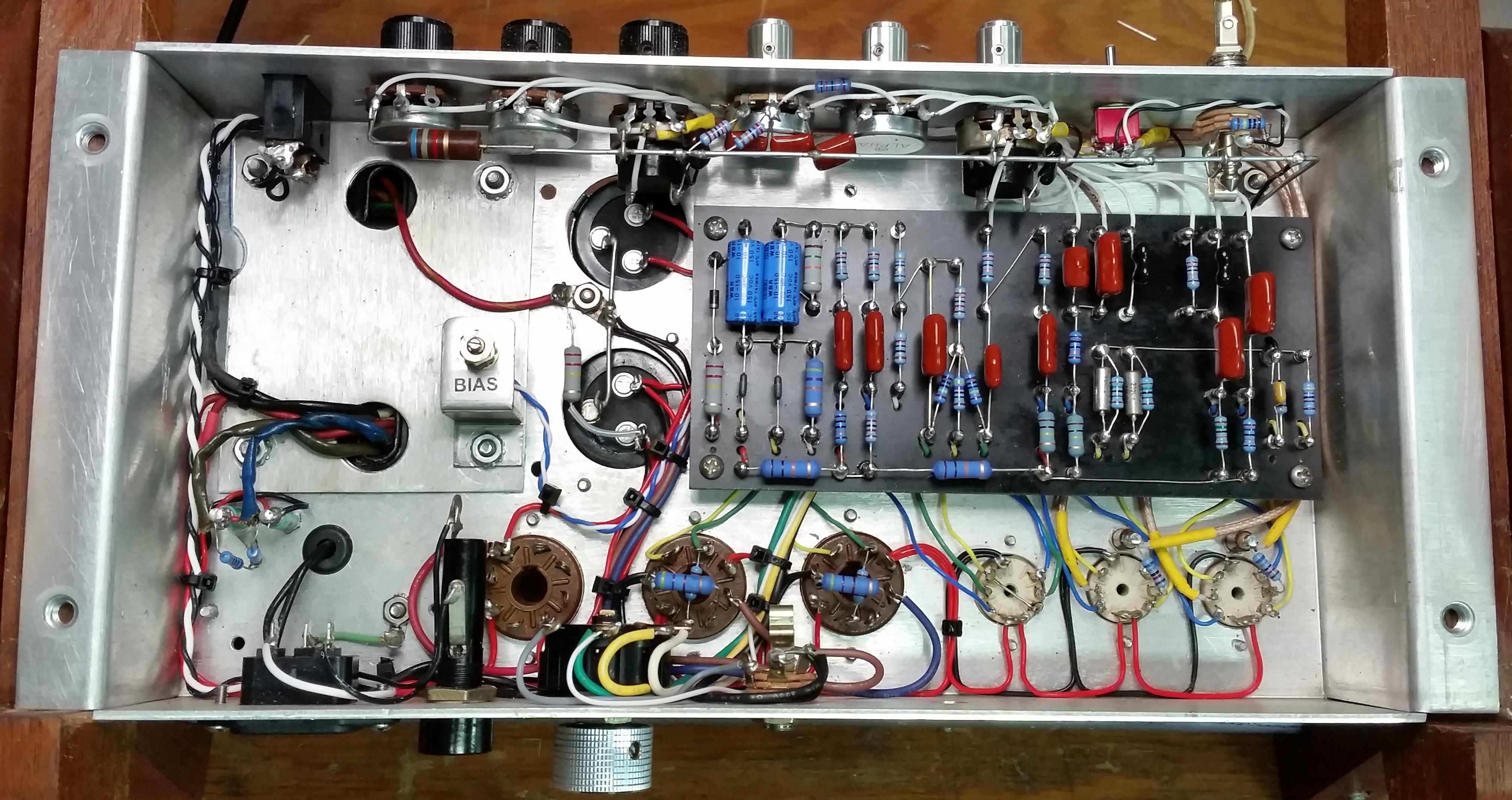
There's the working guts.

The start-up process went well - no smoke, no blown fuses. I biased a matched pair of newer J/J EL84s on the cool side, checked voltages again, and plugged it into my single 12 cabinet. It made sounds, but didn't quite sound right, and I trace the problem to a shorted cathode on the second tube. I neglected to trim the lead of the resistor connected to directly to V2 pin 8 after soldering it on, and it was touching the chassis. 

Once I corrected that everything started to feel and sound like I imagined it should: clean and bright, responsive and loud, with no discernable hiss or hum until very very loud. Really nice crisp sound with the Telecaster. The line out and built-in dummy load features work nicely, as do the bright and normal channels and their blending circuit. I mistakenly reversed the wiring of the channel switch so that the "up" side of the toggle is connected to the bottom gain pot and and vice versa (see pic below) - it will be a pain to fix, so I might just leave as is. 


It will take me a while to get used to the interactive tone controls. For example, the range and effect of the "mid" knob depends somewhat on the position of the "bass" and "treble" knobs, and likewise for all of them. 

The overdrive sounded was, well, just not very good - sort of weak and scratchy - and I remembered that I had introduced a voltage divider coming out of the OD gain pot to bleed off some signal prior to the tone stack driver, because the simulation and calculations showed that the signal would be way too much for the next stage. That was just wrong. I un-did the voltage divider and it sounds much better now - hotter and juicier as one would guess, but it doesn't overwhelm the next stage like I imagined it would. I'm not sure I like the overdrive sound though - it creates its distortion by saturating the following triode, producing a hard-clipped, squared off signal. This is intentional, and some players like that sound - I will have to play around with it to see whether there is something in there for me. If not, there are strategies for softening and smoothing this kind of distortion that I can try, but any modifications to that part of the circuit will also affect the clean sound, so I may have to do some experimenting. On the other hand, these amps are known to be very good at accepting pedals, so perhaps this amp is good starting point for experimenting with pedal distortion effects.

Looking forward to lots more playing through it to understand it better. Tomorrow I'll try playing the MC5 through it.


Thursday, August 26, 2021

Planning

 It's been clear from the start that planning is crucial to a successful build, probably regardless of how you measure success, but especially for me since I'm so easily frustrated and flustered by mistakes. This amp seems particularly unforgiving of poor planning compared to the first two amps. I've done a lot of planning and prep for this one, but I think there have been at least a dozen times I have started to do something semi permanent - drill a hole, solder a connection, spec-tighten a nut - and paused to think one last time about the next few steps to come, and realized I should NOT do the thing I was about to do. The Hiwatt layouts from the early days are certainly different than the two I've built (based on Hoffman Amps' layouts strategy) and most others I've seen, and I'm guessing the two separate circuit boards, the front to rear combined with right to left circuit flow, and the limited two-row main circuit board requiring lots of underboard jumpers and connections, all contribute to the practical complexities of this build. However, for each time I caught myself before making an error, I've probably made two others that could have been avoided with a bit of forethought. 

Hopefully I'm improving... mainly, I suppose, for the sake of exercising my problem solving and planning skills generally, as it's hard to see building another amp anytime soon... probably the last amp for a while... just don't need another one... nope.

Recent progress

Populated main board and soldered all finished connections, leaving those points connected to off-board components unsoldered: 


Completed the impedance selector, speaker out, line out bits:


Input jack, channel selector, channel gain pots, overdrive push-pull selector pot:


Tone, master volume and presence pots pre-wired and installed:


Now I'll do as much testing as I can just to make sure there's circuit continuity at least, and to make sure all the pots work in the right direction, and that all solder joints are good. Then I'll install the main board and complete all connections. 


Friday, August 20, 2021

Design and Build Progress

Been chipping away at it. 

I decided to make the circuit (turret) boards myself since, for this build, they are pretty straight forward, and I have the materials, so why not. I was delayed on starting due to a few bits of missing hardware (screws and nuts, cap clamp, wire), but was able to get going recently. After reviewing my schematic for about the 50th time, and validating it against my layout plan, I started the build and have made good progress, with no big problems so far.

(schematic v.8.3)


(layout v.8.3)

I started with the transformers, power supply and pilot light.

(Power supply, On/Off switch, fuses, pilot light wiring)

(Transformers installed for real and leads pulled and trimmed)

(turret boards dry-mounted) 

Then the tube filaments. 

(red and grey wire pairs serving the heaters for each tube socket)

And recently completed populating and installing the power amp circuit board. 

(top view of rear board in progress)

(bottom view of rear board)

(rear circuit board installed, power tube sockets wired)

I also completed the wiring of the power tube sockets and the DC power supply up to the second filter capacitor. I was getting odd results when doing some early testing, and discovered that the power transformer doesn't really start working like it should until you connect in the first reservoir capacitor.  Once I did that I was able to confirm my bias and heater elevation circuits were working as designed, and got expected voltages (much higher now with no working load than they will be later) at the power tube plates and screens. 


Friday, August 13, 2021

General Design

My requirements are roughly:

As many Hiwatt genes as possible, including layout and dress, which means:

- Front to back circuit flow like the 70's era DR504s 
- Running wires as rectilinearly as possible, bundling them like Harry Joyce.
- Fixed bias power section and fixed bias Long Tailed Pair (LTP) phase inverter.
- Clean and loud class AB power section that breaks up only at high volumes.
- Two channels, "Brilliant" and "Normal"
- 70's era tone stack and presence control.

Other design features:

- Single input, with isolated and blended channel switching. 
- Switchable pre-amp overdrive.
- EL84 power tubes.
- Elevated DC reference for filament heaters to reduce noise.
- Line out and safety load for use without speaker plugged in.
- Adjustable power tube biasing and exterior test points.

So, I'll make my layout as close to Mark Huss' 70's clone  as possible, while accommodating my own additional requirements. 

(Mark Huss' DR504 circuit and component chassis layout plan)

Here are some early sketches and process pics of my attempt at doing that:

(chassis general layout and drill plan)

(parts mockup - top)


Friday, August 6, 2021

Hiwatt Genes

At it again. Having built a vintage Fender-based circuit (the Scarlett) and another one incorporating slightly more modern ideas (the 2SE), I've gotten interested in the Hiwatt story. Mark Huss's website provides useful history and technical information, and of course, I love the sound of the classic rock and roll recordings made using these amps from the 60's and 70's. So, building something with Hiwatt genes, that gives me yet one more distinct guitar tone to choose from, seems like a good next project.

But without making a complete clone - sourcing identical parts and making an exact copy of the original - can one actually build something that sounds similar to the original? I'm doubtful, yet I don't what to invest a lot of money in getting those parts (e.g. the transformers are $300 - $400 each) when I have a bunch in basement, left over from the original cache I received from Michael last year. There are, however, some design features and build techniques I can use that I think may contribute to a Hiwatt-like sound.  I am also interested in having an amp that uses lower powered output tubes, such as a pair of EL84s (compare about 18 watts output power to the 35-40 watts produced by the 6L6 tubes in the Scarlett), and there are plenty of good power section designs out there to draw from. While Hiwatt did eventually design an amp around these smaller power tubes (SA20, Custom 20), that wasn't until after the founder passed away and the company was sold in the late 80's, so these newer amps and don't really have the classic sound of the amps they produced in the 70's. In any case, I'm looking into a design that might incorporate those things.

Good schematics of various Hiwatt models can be found here and here, and there are lots of pictures of originals and good reproductions to draw from. I'll build a head-only version with a pre-amp section based on the DR504, with a selectable built-in overdrive option based on the DR Overdrive Lead (DROL). There's a Hiwatt-like kit that was made by Trinity Amps that has some of the same features I'm interested in, so I'll borrow from that design and try to use as many of the early 70's classic layout and circuit features as possible, while reducing the power of the output section from the usual 50 watts to 20 and adding a few other features, like a transformer-tapped Line Out (for bi-amped wet-dry effects option), DC-elevated filament heaters to reduce noise, and separate and blendable input channels.

Here's my schematic of the hybrid circuit I've developed, with notes:


Thursday, July 8, 2021

Calling the Stereo Single Ended (2SE-5881) done

Lots of playing and tweaking in the past couple of months. 

First, it's sounding good and markedly different with each of my main guitars, and it looks good... er... rather, it looks innocuous, like a proper amp.  It's fairly noise-free, but not dead quiet (I will go back in at some point and re-line the chassis area of the cabinet with ground-able foil), and a little hissier than Scarlett. It provides decent clean tones and a unique overdriven lead sound, and has plenty of volume for most club venues. 

(final circuit, with new filter node, new shielded runs)

(Still needs new panel labels)

(rear view)


PRE-AMP

Nice clean tones from the two-stage 12AY7 input channel up to nearly full pre-amp gain settings - the Telecaster has slightly "cooler" pickups so doesn't drive the first stages quite so hard and develops just a slightly hairy shimmer at full gain on the dial, whereas the MC5 gets a bit more crunchy with the input gain at 10, especially in humbucker mode. The tone from the preamp is somewhat thin at gain levels lower than 6 on the dial, for both guitars, but the audio spectrum fills out quickly from there and stays crystal clear until 8-9, when it starts to break up.  

The Bass, Mid and Treble tone controls are very interactive and while I can eventually dial in a good balance of highs, mids and low end, I do wish the controls were deeper in each of their respective bands. I may try increasing the cathode bypass capacitor on the input stage to boost the bottom end, but need to be careful as this will impact the overdrive stage as well, which doesn't want to see a lot of low frequencies.

The tone controls function by dumping various frequency ranges of the signal to ground, reducing the overall strength of the signal. The pre-amp boost (PAB) switch works as planned, inhibiting the cutting of any signal. The result is a nearly full raw signal passed without any tone shaping. So far I haven't found this useful as the signal is too bright and sharp without some shaping. Again, this may be improved by upping the cathode bypass cap, but it's not a priority. In this case, the feature was not worth the effort of providing its own footswitch, LED, and relay, but it was a good experiment.  

OVERDRIVE

Another pair of 12AY7 triodes, lots of local negative feedback, and another tone control shape the sound produced by this stage. Even at lower gain levels, this part of the circuit gives the signal more sustain and is moderately but not overly mid-focused. This stage is fed entirely by the pre-amp, so gain in that stage directly drives the input gain of the OD stage - when the pre-amp is dialed up to 7 or higher, the signal produced by the initial stage of the OD rounds off nicely, producing a softly distorted tone. The second stage of the OD section is then controlled through the "Drive" knob, which produces a "thickening" of the tone and then additional distortion from about 5 and higher on the dial. The tone control works well to dial down high end harshness. Not surprisingly, settings here also really depend on the guitar used, the pickups selected, and the tone control settings in the pre-amp section.    

FX LOOP

This feature works amazingly well... hard to believe actually, since I don't fully understand the principles of signal to circuit impedance and there are no definitive best models of this kind of thing. I made some educated guesses about how this part of the circuit should look, and it just works. The Line6 HD500 stereo effects unit does its part well also, and presents what seems to be a suitable signal to the power section drivers. I can return a left and right stereo effects signal to the amp, or a single mono effect signal to one channel leaving the other channel totally "dry", with only the unaffected signal from the amp, in a wet/dry configuration. This wet/dry setup preserves the amp's touch-sensitive immediacy and sharpness in one channel, which is reduced when the whole signal is sent through the HD500 (it's subtle, but noticeable to the player if not the listener), while also providing effects in the other channel.

The two effects pedals I have don't work well in the FX Loop, but I haven't really tried to address that since I use the HD500 unit. This has to do with impedance matching and buffering, but as I said, I don't have a good enough theoretical grasp on it to explain.

POWER SECTION

It's a pair of separate individually operating output amps, each fed separate signals from the FX return part of the circuit.

(basic block diagram of amp function)


The 5881 tubes operate at somewhat lower power than Scarlett's 6L6CG, which means they are slightly quieter, and have slightly different tonal and distortion characteristics. I tried a pair of 6L6s in this amp and they sounded anemic and empty by comparison. I think this means my choices for output transformer (Fender Princeton style, 15W) and driver configurations that were made with the 5881s in mind, turned out to be right... or right enough, since I have little experience to compare. The drivers (12AX7) put as much as 25vac (rms) of signal (1KHz test) onto the grids of the 5881s, which is plenty to drive them past their range of linear operation (up to about 18vac peak), and both clean and OD amp settings produce a gradually breaking up and progressively more compressed tone. Pretty much all that I hoped for.

(Tube set in modified donor chassis) 


Measurements (using my nifty new scope, see below) show this amp provides about 10 watts clean to each speaker and up to about 15 watts max (actual power output varies across audio frequencies).  

SPEAKERS

I started with one stock Fender speaker from the donor amp, and one 10" rock-oriented (mid-focused) speaker, just to get sense of tonal range and response. This amp, as well as Scarlett, are capable of producing nice cleans as well as moderate gain tones, so I wanted to support both. Initial tests with the first set of speakers gave me enough info and confidence to select a pair of nicer speakers to support a broad range of sound, so I currently have a Jupiter 12LC and a Weber DT12, which sound great separately and blended together. I configured the combo to allow them to run separately or in series, so while they are mounted in the combo, either amp can be plugged into one or both of them.                   

BUGS

There's a niggling problem I haven't been able to solve. Here's an initial query I put to one of the amp forums I look at, back in mid June: 

"[...] A version of the input signal from the preamp, and especially from the OD section, is appearing on one grid (Left side, V3 pin 2) of the power section driver, and is loud enough at high gain settings to make FX loop volume pedal (as well as the Fx send pot) ineffective for shutting down the sound. The other grid (V3 pin 7) is almost dead quiet and seems to work as expected. The frustrating part is I don't understand why the difference between the two identically configured channels. The offending channel is a little closer to the preamp circuitry, but moving the wires around doesn't really confirm that is an issue. There are slight differences (< 5vdc) in the two plate voltages for V3, though I'm not sure how that could be significant. All of this is compounded by my lack of real understanding of capacitive vs. inductive coupling (presumed related to the problem?), and my general inexperience with with circuit design."

And here's my final post on it a few days ago:

"This issue is beyond me.  I've updated the power supply nodes, checked and re-checked lead dress, added shielding to vulnerable leads, tested additional coupling caps. Thanks to your suggestions, I do think the rogue signal is coming in through the plate of the driver (V3b), but I'm out of ideas and energy for it. The truth is, it's more of an annoyance than a practical problem: it's significant in the left channel at very high gain only, and only when I'm trying to shut down the signal using a volume pedal in the Fx loop. It's just not a problem at all in the right channel (which is exactly the same as the left! ugh!), so if I need to, I can just mic up that speaker for recording and silence the other.  Thanks for all the help and suggestions!  On to the next..."

To help track down the problem, and trouble shoot circuits in the future, actually got my hands on an old analog oscilloscope, which has been fun to learn and play with... it did provide some useful data for ruling out possible causes, but (this one) can't be used to look at audio (AC) signals mixed with high voltage DC, which is what's going on.

(soft clipping on the OD signal) 


So, overall, the amp's not perfect, but it's pretty darn good, and covers different sonic territory than Scarlett.  I'll work on getting some decent audio clips together to update this post. 

Final design doc link. 

I've discovered that FedEx/Kinko's will custom print fairly cheaply on adhesive weatherproof vinyl, so I'll likely give that a try for making a new set of labels for the front panel, that actually match the knob functions. 

THE THING IS

The thing is, I still have a very nice Classic Tone output transformer, a salvaged 8"x16" chassis, lots of pots, resistors, caps, and other bits and bobs laying around that are just going to waste sitting there... I have always loved the HiWatt sound (David Gilmour, Pete Townsend, Joe Walsh, etc.), so...


Monday, May 3, 2021

Further exploration

So, have been putting the new amp through its paces, learning its voice and how it interacts with the MC5 and the Line6 Pod HD effects unit. Tonally, it's a lot different sounding than the first amp ("Scarlett"), of course: much more mid-frequency focused, no doubt due to the cathode bypass capacitor and coupling capacitor values that reduce the low end, and the cool-biased, all-12AY7 (tube type) pre-amp seems to compress the dynamics a bit, so note attacks and articulations are a bit softer. And while it is bright enough sounding, it doesn't have Ruby's sparkliness in clean settings.  The range of tone settings of the preamp feels a bit limited compared to Ruby, but that may have more to do with the aforementioned bypass and coupling caps, than the components of the tone section of the circuit. Nevertheless, I may try reducing the value of the capacitor governing the mid pot, to roll off a bit less of the low end there. At about 7 on the preamp "gain" dial, the clean tone develops a nice edge to it, and progressing up to 10 adds a slight crunch when I dig in to a string, especially in humbucker setting on the MC5. That said, I'd still characterize it as remaining quite inside the realm of "clean" for single coil and non-aggressive playing. Just as I hoped it would.

The OD (overdrive) circuit is fascinating, though I'm still figuring out how to consistently get sounds I like from it. As you may recall, it is a cascading pair of triodes (again, 12AY7) which takes its signal input from the output of the preamp. When the preamp gain is high, the OD input is also high and can drive the first OD triode to the point of clipping, or flattening, the highest amplitude portions of the audio signal. But with the preamp at lower gain settings - below 50% - the first OD triode gain remains mostly linear and simply shapes the tone of the signal, further reducing low frequency content and softening the highs. The "drive" dial controls the amplitude of the signal coming from the first OD triode and presented to the second, and allows fine control over further distortion of the signal, from a very clipped high gain sound (depending to a large extent on the shape of the incoming signal) to a fairly clean punchy mid-boosted sound. After that, a single "tone" dial allows for attenuating the high frequencies and preserving the lows, and a "level" dial adjusts the final signal strength passed back into the main circuit. 

Using the Line 6 HD-500x signal processor for adding effects such as stereo reverb, delay, L/R panning, etc., in the FX loop part of the circuit has worked well so far, especially considering the range of input voltages is has to handle, from a few hundred millivolts to a couple of volts. The HD apparently adjusts automatically to the incoming signal impedance. This is not true of the pedal effects I have, and they do not work well in the FX loop. I can run the single channel "send" to the HD and return a right and left stereo signal to the power section, or return just one channel from the HD as a mono effect, and leave the other channel dry (un-effected). Both methods work well, and as planned. 

The power section stays quite clean and crisp up through reasonable volumes and only begins to break up at ear-splitting levels. With the attenuator (Fryette PS2) in place to keep the final output volume down, I can activate one channel and dial the power section up to the point of near break-up, which is a nice sound - probably one I would use for recording, but not in a live setting because it's requires too much fiddling around. Here's the circuit in its current implementation (without the power supply):


I recently received a new speaker to try in place of one of the stock 12" Fenders that came with the FM212 salvage amp. Based on my positive past experience with a 2x10 stereo combo, I opted for a 10" speaker that is shown to have a relatively balanced response: the Eminence Cannabis Rex. I created and installed a second baffle behind the existing one on the right side of the amp, mounted the speaker, and have been playing it on its own and in combination with either the stock 12" Fender mounted in the left side of the amp, or an EV-L 12" mounted in a separate Thile-optimized cabinet. I like the new speaker so far, but I'll have to do some recording and listening back to be sure it's what I'm aiming for.


(new 10" speaker test)


Saturday, April 24, 2021

Initial testing

I fired it up with the "lamp limiter" in place (200w lightbulb in series with the incoming AC power, allows full voltage, but limits the maximum current that can be drawn by the amp, preventing damage from major shorts, etc.), first with no tubes, then with tubes installed... No smoke or fire! always a welcome sign. I measured voltage in some important spots and found things to be in line with readings from my test board set-up. Here's the working circuit:


Removed lamp limiter and plugged in a guitar, and (once again, shockingly) everything seems to work as it should. Stereo master volumes, OD channel and pre-amp switches work as expected, all controls, work fine. Well, almost - I had to fix one error, and make one adjustment: I had mis-wired some jumpers on the left and right channel volume pots such that the dials worked in reverse - an easy fix. Also, because I implemented a slightly different DC filter design than I had in my test board, the screen voltage on the power tubes was lower than expected, lowering the max output of the tubes, and (as we learned in an earlier post) compressing the signal slightly. So I reduced the resistance in one part of the filter circuit, and that fixed it. Here are some "final" pics, tho the OD circuit will probably need some tweaking as I play with it more.


(rear view of chassis)

... with chassis installed back in the cabinet.


Wednesday, April 21, 2021

Details

I'll have to digress slightly at this point to acknowledge some things. 

The folks who make this stuff look easy, repeatedly, are truly master crafts-people. That may be obvious to some, but for me - a habitual, sometimes recovering, scoffer - I admit it has taken a while for this to really sink in. I continue to struggle, after many months of trying, to keep things straight and neat, to work efficiently, to make sound and consistent solder joints, and to layout my circuits in a way that supports ease of assembly as well as a short signal path. Even working slowly and deliberately, completing just one task to the level quality that I'm aiming for, is a rare thing... and there are hundreds of such tasks required in succession to build a high quality piece of gear. It borders on frustrating at times, but only for a moment, and then I realize it doesn't matter how long it takes, or whether some theoretical customer would  be happy with it. Mentally, I am so habituated to pursue optimization of cost (time), features, and quality, that it takes real focus to shift away from that holy trinity of commercial product development toward something more personally nourishing... the optimization of time spent with my sweetheart, enjoying the process of learning, solving, and creating, and being ever more mindful of my role and responsibilities in the family of earthly things. 

My understanding of "Lead Dress" is that refers to the concern for and execution of proper placement of wiring and components to achieve desired circuit dynamics and audio results. It isn't just precise adherence to the circuit design or the neatness of the installation, though both of those are critical for a successful build. Rather, it's a very deliberate approach to the organization and connection of parts that sounds best/right, and results in a physically robust build that is straight-forward to maintain. Making good lead dress takes a lot of practice. Here are some links to examples of solid lead dress. 


(Michael's amp)


(Hoffman Blackface Deluxe)


(Trinity Tri-watt)


(Sluckey Amps All American Dual Lite)

Good looks and stage appeal, while not required, also don't hurt. It's enough to be masterful on the electronics side, but some folks are also excellent wood workers, upholsterers, and visual designers as well. Three more areas in which I know just enough to injure myself, yet lack the depth of skills and patience required to produce something of value to anyone other than myself... which gets back to the previous point regarding this whole enterprise being about process and learning and less about specific outcomes, I suppose.

So, lots of progress since last post: 

Rigged up a mounting bracket and two LEDs to work with the two relays using the tiny holes already in the front panel: 


Pre-wired and installed all front panel controls:


Wired the main circuit board and set components:


Installed circuit board and connected all leads to controls and sockets:


Pre-start up sequence and testing is next. Then we'll see how it sounds...